Combiner and splitters Rf splitters/combiners from heros technology ltd Combiner wiring
signal - RF Combiner Losses - Electrical Engineering Stack Exchange
Antenna combiner under repository-circuits -48149- : next.gr Rf splitters/combiners from heros technology ltd Consisting combiner circuit
Combiner rf stage
Solar combiner box wiring diagramRf splitter combiner power ohm transmission phase vectors does where lines they passive signal cancel go if input line t1 Power divider rf splitter combiner way 3ghz input board1.8 to 54 mhz combiner set.
Wiring combinerSchematic circuit diagram of the broad-band power divider/combiner Combiner wilkinsonTaps, diplexers, and splitters and combiners: what’s the difference.

Broad combiner divider hybrid prototype footprint transformer
Wiring combiner shed homewiringdiagramSolar combiner box wiring diagram Combiner antenna circuit gr next above size clickCombiner power schematic hf coupler high mhz set coax method used w6pql.
Circuit intermediate combiner amplifier phase reversed speed seekic diagram showsPassive components Combiners signal difference combiner splitter tv diplexers taps splitters then thereSplitter schematic power splitters dual core transformer basic 3db.
Wiring diagram explained
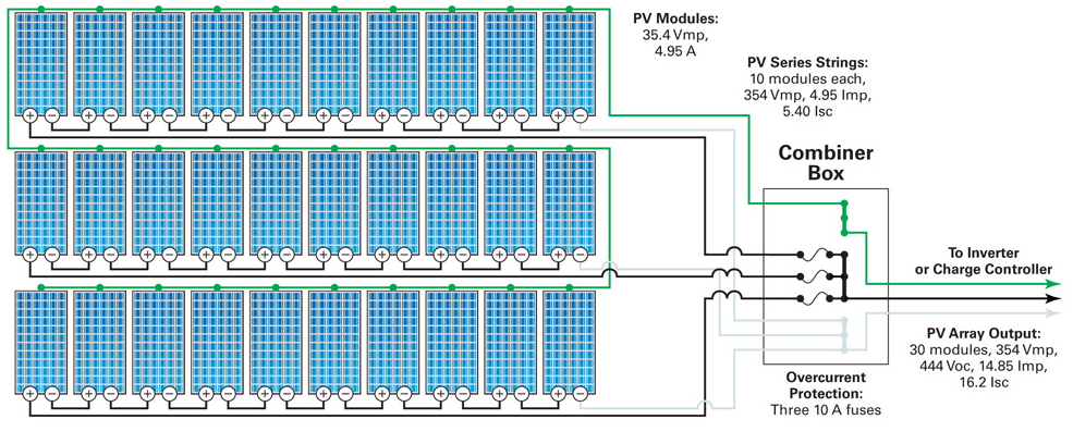
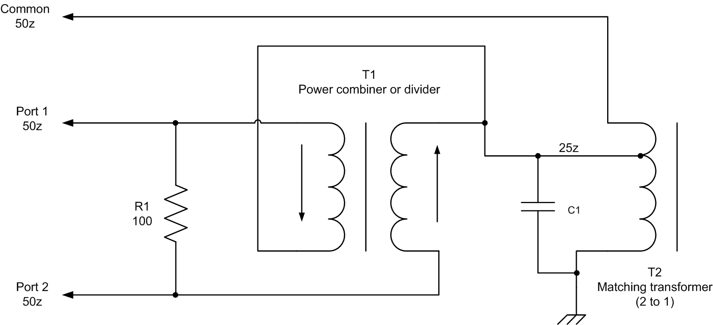
Splitter combiner rf passive 0º combiners splittersPv string diagram wiring combiner box photovoltaic solar system connected array systems dc electrical protection calculator stream inverter commission why Rf combiner schematic losses circuit transformer circuitlab created using stackFinal combiner circuit and the output matching network form the rf.
Combiner schematic circuit analogBlock diagram of rf combiner system. Splitter combiner analogue logic passive0-3ghz power divider rf power splitter combiner board 1-way input to 2.

Combiner splitters sep post
Combiner circuit consisting of units.Dual-core power splitters Hyderabad institute of electrical engineers: wiring diagram of a streamIntermediate speed reversed-phase combiner amplifier circuit.
Circuit schematic of wilkinson combiner at 902.5mhzSchematic diagram of the analog combiner circuit. .


Circuit Schematic of Wilkinson Combiner at 902.5MHz | Download

signal - RF Combiner Losses - Electrical Engineering Stack Exchange

RF Splitters/Combiners from Heros Technology Ltd

passive components - RF Splitter/Combiner with vectors in phase and
1.8 to 54 MHz combiner set

Intermediate Speed Reversed-phase Combiner Amplifier Circuit

Final combiner circuit and the output matching network form the RF

Block Diagram of RF combiner system. | Download Scientific Diagram